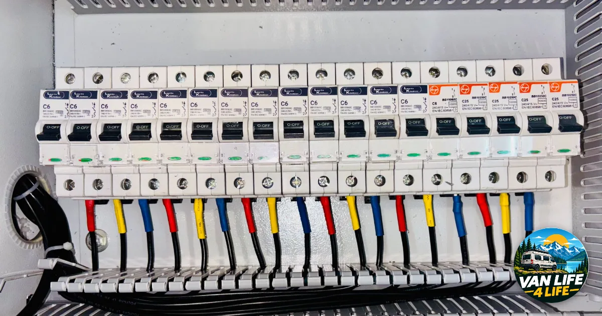
A campervan wiring diagram is built outwards from the battery: a main fuse on the positive side, an isolator switch, a distribution busbar, then one fuse per device, and on the negative side a shunt fitted just before the battery. Every cable gets a fuse sized to protect that cable, and its cross-section depends on the current it carries and the distance it runs. This guide sets out that order component by component, using Victron Energy’s rules on voltage drop and protection.
1. Positive side of the wiring diagram: battery, main fuse, isolator, busbar, one fuse per device or charger.
2. Negative side: battery, shunt, negative busbar, with every device connected after the shunt.
3. Aim for a voltage drop of 2.5 % at most, which is 0.3 V on a 12 V system, and size each cable to suit.
What goes into a campervan wiring diagram
A van’s wiring diagram brings together two groups of parts. Charging sources fill the battery: solar panels through their charge controller, the alternator through a DC-DC charger, sometimes a mains charger at a caravan site. Loads drain it: lighting, the fridge, the water pump, a 230 V inverter. In between, the 12 V circuit has three jobs: share out the current, protect each cable from overheating, and measure what goes in and out of the battery, a job that sets the order of the parts. Have your chosen battery capacity to hand, for example from our guide on how to size a van battery bank, along with the maximum power of each device.
The most thorough reference on the subject is Wiring Unlimited, the free wiring guide published by Victron Energy and written by Margreet Leeftink. The rules quoted here come from it unless another source is named.
The positive side of the diagram, battery to devices
The first component after the positive terminal is the main fuse. Victron Energy is clear on this: every consumer connected to a battery needs to be fused, the fuse sits in the positive cable, and a DC circuit usually has a main battery fuse after which it branches off to individual devices.
With a lithium battery, that fuse has an extra requirement: Wiring Unlimited states that at least one fuse in the DC line must have an interrupt rating equal to or greater than the maximum short-circuit current the battery bank can deliver. The guide lists very different ratings across fuse families: 200 kA for an Eaton Bussmann Class T fuse, 2,500 A for a 70 V Littelfuse MEGA fuse. Check the figure on both your battery’s datasheet and the fuse’s.
Next comes the isolator switch, which only isolates the positive cable and is not always essential since pulling the main fuse also isolates the battery. After it, a busbar gathers the outgoing circuits: not insulated, so Wiring Unlimited suggests covering it, for instance with a sheet of Perspex. On that busbar, each circuit gets its own fuse, and solar follows the same logic upstream of the charge controller.
The negative side of the diagram and where the shunt goes
In the wiring diagram, the shunt is the part that tells you how much charge is left: it measures all the current passing through, so its position is strict. Victron puts it in the negative cable as the last component before the battery bank, and states that every load and every charging source must connect after it.
FarOutRide describes the same layout in its guide to a van electrical system: anything wired straight to the negative terminal bypasses the measurement, and your battery monitor then shows the wrong state of charge. The shunt needs sizing too, to handle the combined maximum current of everything connected, and it is often the inverter that sets that rating.
Sizing cables and fuses in the wiring diagram
On a wiring diagram, a cable that is too thin heats up and loses voltage. Victron advises aiming for a voltage drop no bigger than 2.5 %, which works out at 0.3 V on a 12 V system. FarOutRide allows a little more: 3 % for critical loads and 10 % for non-critical loads such as lighting. Both agree on the length to count, the full round trip of the current, positive cable plus negative.
For cables up to 5 metres, Wiring Unlimited offers a shortcut: divide the current by 3 to get the cross-section in mm² (its own example, 200 A, gives 66 mm²). A few rows of the guide’s table are below, showing the maximum current for each total round-trip length.
| Cross-section | 5 m | 10 m | 15 m |
|---|---|---|---|
| 6 mm² | 18 A | 9 A | 6 A |
| 16 mm² | 48 A | 24 A | 16 A |
| 35 mm² | 105 A | 53 A | 35 A |
| 70 mm² | 210 A | 105 A | 70 A |
A fuse protects the cable first and the device second: for a single load, it matches either the device’s current or the cable’s rating, whichever is lower. Here is a worked example for your own wiring diagram, to swap for your own figures: a circuit carrying 60 A over a 4-metre round trip gives 60 ÷ 3, or 20 mm², rounded up to the next standard size. The fuse then goes below that cable’s rating and above the device’s normal running current.
Chassis earth and the mistakes that skew a diagram
The van’s chassis counts as an earth in Victron’s terms. Wiring Unlimited says to make that earth connection close to the battery and never to earth the positive or negative of the solar array; FarOutRide adds scraping the paint off at the fixing point. Three mistakes stand out in most wiring diagrams: wiring a device straight to the battery and bypassing the shunt, a main fuse without enough interrupt rating on a lithium battery, and forgetting that fuses, shunts and poor crimps all add resistance to the circuit.
Your wiring diagram by type of build
| Build | What to plan for |
|---|---|
| Weekend van, lighting and USB | Main fuse, positive busbar, fuse box, shunt on the negative, cables sized for a 2.5 % drop |
| Regular trips with solar and a DC-DC charger | The same, plus a fuse between panels and controller and one fuse per charger on the busbar |
| Full-time living with an inverter | Shunt and main fuse sized for the inverter’s peak, interrupt rating checked for lithium |
Draw your wiring diagram in this order, from the battery’s positive terminal to the last device, then back through the negative and the shunt, labelling every cable with its current, round-trip length, cross-section and fuse. If you have not chosen your solar panels yet, our guide on how much solar power your van needs gives you the current to note on the charge controller’s circuit.